Industrial ventilation and fans, physical principles
The physical laws that underline fluid handling and the operation of fans
Physical laws, industrial fans and ventilators
The scope of the production processes is extremely varied. It is also true that most of the productions are united by a necessity: the fluid handling. In fact, if in the process it is necessary the use of liquid or gaseous currents, must be introduced appropriate devices that allows the movement of these currents.
In the case of interest to us, namely the treatment of gaseous pollutants, equipment that allow the handling of gaseous currents are fans and industrial ventilation systems.
The objective of this article is to provide information about the physical laws that underlie the fluid handling and, therefore, the operation of the fans. In particular, we will analyze:
- The conservation of mass
- The energy conservation law
- A practical example, to see how these laws govern the motion of a gaseous flow inside a pipe
Physical laws
Consider a fluid that moves in a given pipe. On it they can be applied two important principles of conservation: conservation of mass and conservation of energy.
The conservation of mass
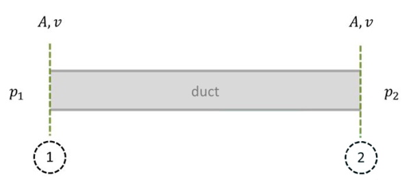
The principle of conservation of mass tells us that the total amount of material flowing inside a duct, provided that there are no secondary feeds or losses, is constant. By applying this law to two different sections of the pipe (which we will call 1 and 2), and taking into account the fact that a massive flow rate ((m)) ̇ can be written as the product of density (ρ) and volumetric flow (V ̇), we get:
This law shows us something very important: if the density in the two sections are about equal, then the volumetric flow rate of the fluid tends to be the same. Stating that the density is about the same, since we are talking of a gas flow, it means considering the non-significant changes in pressure and temperature.
We can make one more step, noting that a volumetric flow rate can be expressed as the product of the velocity (v) and the crossing section (A) of the fluid. Taking this into account, the equation becomes:
From here we deduce another important element: if the density is approximately constant and the section of the pipeline does not change its value, then the speed of the fluid is the same in the two sections. This is a very important aspect, which we serve in the subsequent considerations.
The other principle that we use is energy conservation.
Energy conservation

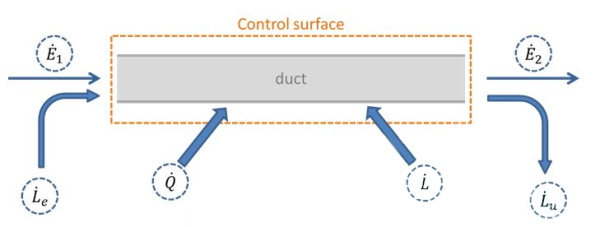
Inside the control surface, that surrounds the pipe, enter and exit different powers:
- E: this type of power is associated with incoming and outgoing massive flows. In particular, each massive flow keep specific energy-related contributions to the internal energy flow , its gravitational potential energy (where g is the acceleration of gravity and z is the quote to a reference system) and its kinetic energy (1/2 v2). therefore
- Le e Lu: Are the energy-related contributions to fans work. The incoming mass flow is pumped inside the control surface by the fluid that precedes it, while the outgoing mass flow is pumped out from the control surface by the fluid present in the pipe itself. These contributions can be quantified as the product of the pressure at the section considered (p) and the volumetric flow of the fluid.
- Q: It represents the thermal power incoming or outgoing from the pipeline. It is typically considered positive when entering.
- L: It represents the incoming or outgoing power from the pipeline due to the action of surface forces, displacement or derived from specially inserted mechanical equipment. It is typically considered positive when incoming, although for some specific contexts can be used the opposite convention.
Considering a stationary situation, in which the total quantity of energy present within the tubing does not vary, it is had that the sum of the incoming power must equal the sum of the outgoing powers. therefore:
We now introduce a number of simplifying assumptions:
- Absence of heat exchanges (Q ̇ = 0). Since the gas does not exchange heat with the outside, its temperature will be uniform. Since, moreover, the internal energy of a perfect gas (in which the air can be approximated) is a function of temperature only, we have that the internal energy in correspondence of the two sections will be the same. So we can simplify it in the balance.
- Absence of power associated with the work of surface forces, volumetric or related to mechanical equipment. Are not counted in this case the pressure forces (already taken into account in and ) and those associated with viscous stresses. In particular, the viscous stresses give rise to a contribution of negative power. We call this contribution ,, and let assume negative sign to highlight the fact that it is an outgoing contribution.
The energy balance thus takes the following form:
Divide now both sides of the equation by the volumetric flow rate, and move the term linked to the viscous stress on the right of the equal sign:
The equation obtained is now of paramount importance. The three terms that appear to the left of the equal and the first three terms that appear to the right of the equal sign are the Bernoulli in terms of input and output conditions. The famous Bernoulli’s theorem states that the sum of these three terms, in the case of motion of an ideal fluid (with the absence of friction phenomena), is preserved. In our case this idealization is not true since we have taken into account the contribution attributable to the viscous dissipation, which tend to decrease the overall energy quantity. In particular, the relationship between the power dissipated by friction and volumetric flow rate is dimensionally equal to a pressure:
This ratio corresponds to the pressure drop in the pipe, and we will call it . This size typically depends on both the properties (density and viscosity) that the constructional and fluidynamics characteristics of the system.
Practical example
Ok, so far the discussion has been theoretical. What are the consequences from the practical point of view? To understand this, let’s imagine the following situation.

Imagine we have a constant cross-section characterized by a pipe (equal to A), and wanting to make it flow through a given gas flow rate. We have seen that, if the thermal exchanges are null and if the pressure changes are small (compared to the total pressure, as often is the case for the pressure drop), the density of the gas stream is uniform, and accordingly also the speed is uniform:
It follows that the two terms in the kinetic equation first analyzed, are simplified between them, and we get:
Assuming negligible the contribution linked to the change in gravitational energy (this applies to small variations in altitude), we can write that:
This equation is of fundamental importance, because it shows us that in not ideal conditions, so that the fluid is moving, it is necessary to have a pressure difference (equal to the pressure drop) between the two sections. In particular, it will flow in the piping of a volumetric flow rate of fluid that gives rise to the pressure drop exactly equal to the pressure difference between the two ends.
To generate these pressure differences are used, of course, fans. In the next article we will examine the various physical parameters that characterize the operation of the fans and which criteria are used for choosing them.
In the meantime, review our Case History to see how Tecnosida® uses suction systems in its achievements!
See you soon!